Hack that LEDARE
Driven by the need for a neat and unique, dimmable and eco-friendly bedlamp, I startet to hack a reasonably priced 12V LED lamp of tpye GU5.3 from the famous Swedish furniture store. Surprisingly enough, this thing disassembles pretty easily without damage (see for the pictures to follow). More surprisingly, it comprises a constant current source IC with adjust pin - tadda! First simple tests hence were the kick off for this project: hack that LEDARE and build that bedlamp.
Inhalt
- System description
- Hack that LEDARE
- Electrical Circuit Schematic and Layout
- Hardware used/ Bill of material
- Firmware
- Bring it all together
System description ↑
Based on the first tests, I wanted to build the system using the LED light or multiples which I had hacked previously. The lamp's features deemed promissing to achieve the following requirements:- turn the lamp on by pushing and releasing of a push button
- increment the brightness by pushing and holding the same button for a while
- turn the lamp off by pushing and releasing the same button
- when turning off, the light should fade out
- realise a left and right side bedlamp with individual light control
The preliminary test had shown, that one LED driver electronics could be recycled for the purpose of driving two of the lighting elements of the LEDARE.
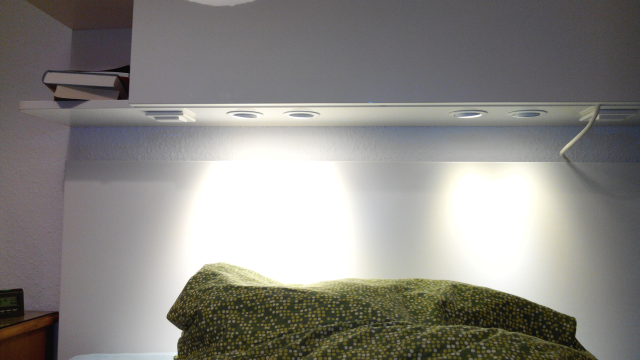
The whole system should be integrated into closed bookshelve that is mounted above the bed's head piece.
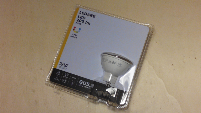
By the way, LEDARE is everything from that Swedish store: the article number - for a bit of precision - is 702.880.22 and is a 3.5W 200lm LED spot with GU5.3 socket. At the point of building this, one lamp costed 3.99EUR.
Hack that LEDARE ↑
Taking LEDARE appart requires two screwdrivers - one slotted and one with Philips head.Before
After
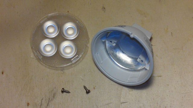
Above: the mechancial parts (from left: cover lense, screws, main frame)
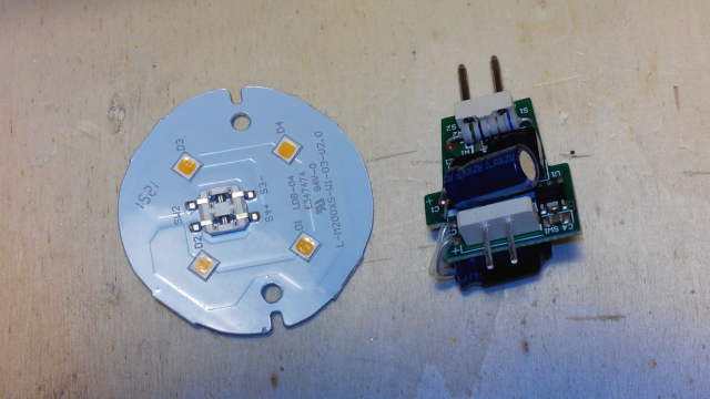
Above: the electrical parts (lighting element, driver PCBA)
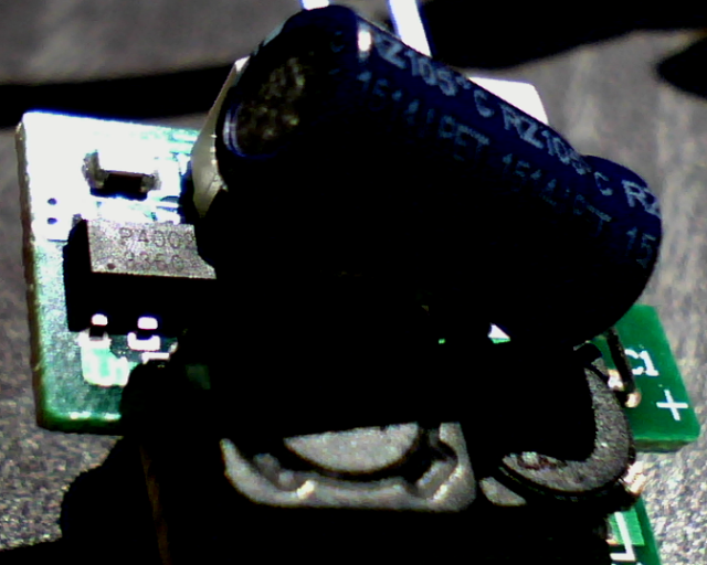
Above: The driver PCB is fitted with a 31LT3360 current source IC from ISSI.
Read the datasheet.
The circuit design of the LED lamp hacks to the following schematic.
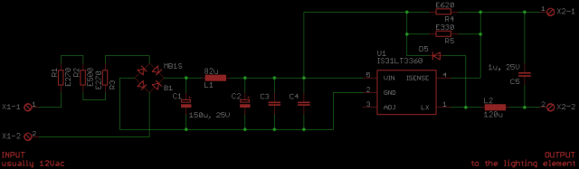
Electrical Circuit Schematic and Layout ↑
Download the latest EAGLE files (schematic & layout):article_hack_LEDAREv01_schematic.zip (zip-container)
Alternatively, get the schematic as PDF:
article_hack_LEDAREv01_schematic.pdf
Hardware used/ Bill of material ↑
The main material for the complete lamp is:- an arduino nano clone (hence an ATMEL ATmega168PA @16MHz *)
- LEDARE 702.880.22 (I used 4 in total, 2 driver electronics)
- a switch mode power supply (MEANWELL, 12V, power output **)
- plastic enclosure
- some wiring and plugs (if you'd like to have easy install and maintain)
- a 5V, 200mA wall sucker to drove the micro
- some chickenfood
- opto couplers (for separating the micro from the LED drivers)
- latching relay (to separate 230V mains from switch mode power supply)
When using the driver PCBA, make sure to short circuit the function of the bridge rectifier by placing jumpers accross the input-output terminals.
As we are using DC as supply (contrary to the original design purpose) make sure to note where plus and minus goes. Another reason for doing so: the ADJ pin would not work.
As we are using DC as supply (contrary to the original design purpose) make sure to note where plus and minus goes. Another reason for doing so: the ADJ pin would not work.
* I used the ATmega168PA developer board (a kind of Arduino nano remake) from Pollin Elektronik with the article number 810 366 (at the point of writing, it cost me 3.95EUR)
** power output should be derived by number of lamps/ driver electronics and adding a 30%...50% overhead.
Firmware ↑
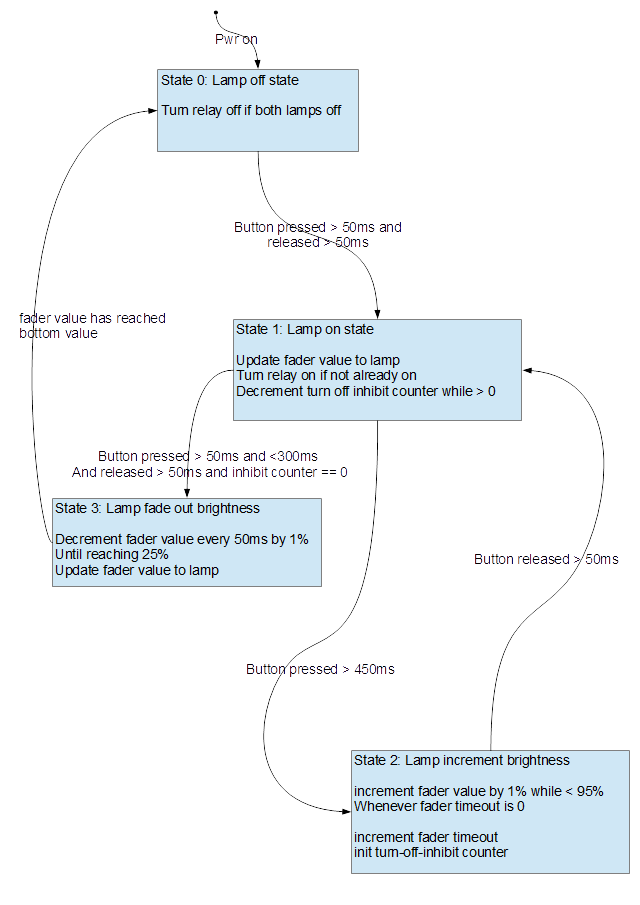
The firmware was initially created with the Arduino IDE until it came to debugging...but lets start with the concept first.The basic principle is built around the logic to continuously read the buttons on the one hand and to control the lamps by a simple state machine. While reading the buttons the desired event is filtered according to the state of the lamps' state machine. The following flow diagram/ state chart shall help make it a bit more transparent.
The firmware itself is based on the Arduino IDE and coding elements of that environment - simply, because the prototyping had been started with it.
As debugging throught the UART became a bit tricky, I switched over to ATMEL Studio 7 which - luckily - just now allows to import Arduino sketches.
Feel free to download my Atmel solution file.
If you do not have ATMEL Studio running, search for the sketch.cpp file, remove the automatically added stuff in the first couple of rows and put it back into the ARduino IDE. I didn't try it and I had no need to do so after a succesful debug session.
Bring it all together ↑
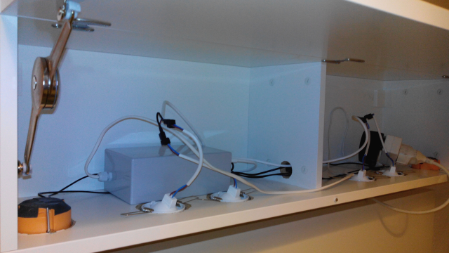
Finally, after having taken every bit together, the goodie looks like that: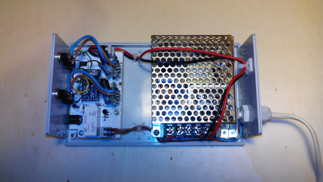
Above: controller board and switch mode power supply in the bottom part of the enclosure - electrical safety first!
A bit more detail on the wiring between controller board and outlets. You might see that the previous connection points of the LED driver now connect to plugs mounted on the enclosure side walls.
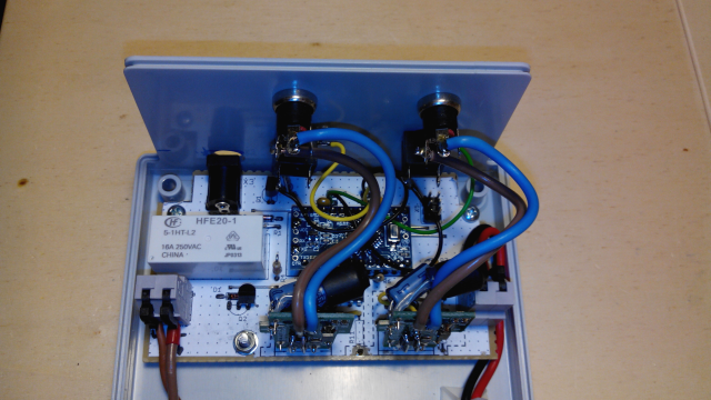
Above: some more detail
To make the installation or even maintenance a little easier I spent some effort on creating some cabeling. As I had not mentioned it before, I'm using two lighting elements (the alluminium boards with the LEDs on) and connect them in series. The LED driver is operated from 12V and the LEDs are 3V only. Consequently, because I could not see any reason for not doing it, driven two lighting elements is feasible.
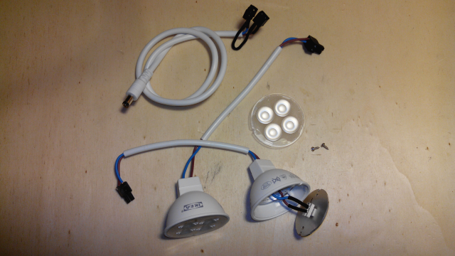
Above: standard barrel jack cabeling with customised connection for two lighting elements, lighting elements refit with cables, detail of wiring (note: there is no more driver electronics in the main frame).
...and finally my use case. Ok, minor touch up is yet pending.